
Imagine yourself, a seasoned farmer, standing before your trusty Massey Ferguson 35. The sun beats down, the air is thick with the scent of freshly tilled earth, and your loyal tractor hums with potential energy. But suddenly, a disconcerting silence. The engine sputters, the lights dim, and the tractor grinds to a halt. What could be the culprit? More often than not, the answer lies within the complex network of wires and components that control every aspect of your machine’s operation – the Massey Ferguson 35 wiring diagram.

Image: schematicdbstrickland.z19.web.core.windows.net
This diagram, much like a blueprint for your tractor’s electrical system, serves as a critical tool for understanding the flow of power, deciphering electrical connections, and troubleshooting various issues. Whether you’re a seasoned mechanic or a curious owner eager to understand the inner workings of your trusty farmhand, a comprehensive grasp of the Massey Ferguson 35 wiring diagram can help you navigate the intricate world of tractor electronics and unlock a deeper appreciation for how it all works together.
Delving into the Massey Ferguson 35 Wiring Diagram: A Comprehensive Guide
The Massey Ferguson 35 wiring diagram, like a roadmap of your tractor’s electrical system, is a detailed visual representation of how components and wires are connected. Understanding this diagram allows you to trace the path of electricity from the battery, through various circuits, to every nook and cranny of your tractor. It’s essential for identifying the correct wiring for each component, troubleshooting issues, and potentially even making simple repairs.
While the Massey Ferguson 35 wiring diagram might seem daunting at first glance, its structure is remarkably logical and organized. The diagram typically features symbols representing various components like the battery, alternator, starter motor, ignition switch, lights, and more. Lines connecting these symbols depict the wires that carry electrical current between them. Each wire is assigned a unique colour code and number for easy identification.
Let’s break down the key sections of the Massey Ferguson 35 wiring diagram:
1. Power Sources: This section concentrates on the engine’s electrical generation and storage. It encompasses the battery (BAT), the alternator (ALT), and the connecting wiring. Understanding this section is crucial for troubleshooting issues related to battery charging, electrical power failures, and starter problems.
2. Ignition and Starting Circuits: This section illustrates the wiring for the ignition system, the starter motor, and related components. It outlines the path of electricity from the ignition switch, through the starter solenoid, and finally to the starter motor, initiating the engine’s power.
3. Lights and Electrical Accessories: This part of the wiring diagram focuses on the wiring for the tractor’s lights, including headlights, tail lights, brake lights, and instrument panel indicators. It also shows the wiring for accessories like the radio, wipers, and other electrical components.
4. Instrument Panel and Gauges: This section highlights the wiring for the instrument panel, speedometer, fuel gauge, oil pressure gauge, temperature gauge, and other sensors providing critical data about your tractor’s health.
5. Fuse Box and Relays: This section highlights the fuse box, which serves as a protective barrier against electrical overloads, and the relays, which act like switches controlling specific circuits. Understanding the layout of the fuse box allows you to pinpoint problems by identifying blown fuses and replacing them.
Deciphering the Code: Understanding Electrical Symbols & Wire Colours
To navigate through the Massey Ferguson 35 wiring diagram effectively, you need to grasp the language of electrical symbols and wire colours. Each symbol represents a specific component, and each wire colour corresponds to a particular circuit or function.
Here are some commonly encountered symbols and their meanings:
– BAT: Battery – The power source of the electrical system.
– ALT: Alternator – Generates electricity to charge the battery.
– IGN: Ignition Switch – Controls the flow of electricity to the ignition system.
– STA: Starter Motor – Used to start the engine.
– FUSE: Fuse – A safety device that interrupts the electrical circuit to prevent damage.
– RELAY: Relay – An electrically operated switch used to control other circuits.
Wire Colours:
- Black: Ground Wire – Provides a return path for electricity to the battery.
- Red: Positive Wire – Carries electricity from the battery or alternator to other components.
- White: Secondary Wiring – Connects to different parts of the electrical system.
- Yellow: Ignition Circuit – Carries electricity related to the ignition system.
- Green: Ground Wire (Sometimes, depending on the tractor model).
Mastering the Wiring Diagram: Tips and Techniques
Now that you’ve got a handle on the basics of the Massey Ferguson 35 wiring diagram, let’s delve into some practical tips that can help you make the most of it:
-
Start with the basics. Before diving into complex wiring issues, get a handle on the core components and their functions within the electrical system. Spend time familiarizing yourself with the location of the battery, alternator, starter motor, fuse box, and other key elements.
-
Tracing the path of electricity. When troubleshooting an electrical issue, use the wiring diagram to accurately follow the flow of electricity from the source to the component in question. Trace the wire colours, identify potential points of failure, and check for continuity.
-
Understanding the colour code. The wiring diagram will list each wire’s colour code and its connection point. Pay close attention to the colours, as they help you identify specific circuits and track electrical connections with precision.
-
Leverage online resources. Numerous online resources can provide valuable assistance in understanding the Massey Ferguson 35 wiring diagram, troubleshooting issues, and accessing repair manuals. Search for specific parts diagrams, troubleshooting guides, and videos on popular platforms like YouTube.
-
Be patient and methodical. While the wiring diagram can be a powerful tool for solving problems, remember that patience and methodical analysis are key. Don’t rush the process. Carefully examine the diagram, trace the circuits, and perform thorough checks before concluding any repairs.
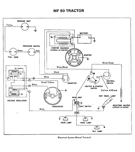
Image: www.yesterdaystractors.com
Schematic Massey Ferguson 35 Wiring Diagram
Conclusion: Empowering You with Electrical Expertise
Understanding the Massey Ferguson 35 wiring diagram equips you with a level of confidence and independence, allowing you to tackle electrical challenges head-on. Armed with this knowledge, you’ll be better equipped to diagnose and repair problems, maintain your tractor’s electrical system, and ensure its continued reliable operation. From identifying a blown fuse to pinpointing a faulty alternator, the mastery of your Massey Ferguson 35 wiring diagram is a testament to the power of understanding and a crucial step towards becoming a more self-sufficient and knowledgeable farmer.
Remember, learning is a continuous journey, and the Massey Ferguson 35 wiring diagram can be a valuable companion on your path to becoming a more confident and adept tractor owner.


