
Have you ever looked at an isometric drawing of a piping system and felt overwhelmed by the multitude of symbols? These seemingly cryptic markings represent a precise language that communicates the intricate details of pipework—from the type of pipe to its connections and flow direction. Mastering these symbols is essential for anyone involved in the design, construction, or maintenance of piping systems. This article serves as your guide to understanding and interpreting the key symbols used in isometric piping drawings, making them less intimidating and more readily understood.

Image: suvivaarla.com
Isometric drawings are a crucial tool for visualizing and planning complex piping systems in three dimensions. They provide a clear and detailed representation of pipework, valves, fittings, and other components. By using standardized symbols, these drawings allow engineers, designers, and technicians to communicate effectively and ensure that the final system is built according to the original design.
Understanding the Basics
Before delving into the specifics, let’s establish a foundation. Isometric piping symbols are visual representations of real-world pipe components. They are drawn according to a set of standardized conventions to maintain consistency and clarity across different projects and companies.
Types of Piping Symbols
At its core, the world of piping symbols revolves around three main categories:
- Pipe Types: These symbols represent the material and size of the pipe. Common notations include:
- Pipe Material: Symbols indicating materials like steel, copper, PVC, or stainless steel.
- Pipe Diameter: Numbers or fractions representing the pipe’s inner diameter.
- Pipe Fittings: These symbols depict various connectors, elbows, reducers, and tees that alter the direction or size of the pipe.
- Piping Components: These symbols represent valves, pumps, tanks, and other essential parts of a piping system. They often include details like the type of valve (e.g., gate valve, globe valve), the pump’s capacity, or the tank’s volume.
Interpreting the Symbols: Key Elements
Piping symbols are like miniature blueprints, conveying critical information through subtle variations and additions. Here are some common elements to look for when reading these symbols:
- Line Thickness: The thickness of the line typically represents the diameter or size of the pipe.
- Arrowheads: Indicate the flow direction of the fluid through the piping system.
- Labels: Letters, numbers, or abbreviations provide additional information such as pipe size, material, or component type.
- Dashes and Lines: Different types of dashes and lines are used to further clarify the type of connection, whether it is a threaded joint, a welded seam, or a flanged connection.
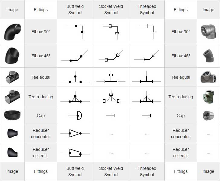
Image: www.wermac.org
Common Piping Symbols and Their Meanings
Let’s dive deeper into the specific symbols most commonly encountered in isometric drawings:
Pipe Symbols
- Straight Pipe: A simple continuous line represents a straight section of pipe.
- Elbow: A bent line, usually marked with a small arc or a curved arrow, indicates an elbow joint, changing the pipe direction.
- Tee: A ‘T’-shaped symbol representing a pipe fitting that splits the flow into two branches.
- Reducer: A symbol with a widening or narrowing line shows a pipe reducer, changing the diameter along the piping system.
- Cross: A plus-shaped (+) symbol denotes a cross fitting, allowing for four branches to connect.
Valves
- Gate Valve: Usually depicted as a wedge or a rectangular shape with a line across it. Allows full flow when open and creates a complete seal when shut.
- Globe Valve: Often represented by a circle with a vertical line through it. A globe valve provides precise on/off control and has a lower capacity than gate valves.
- Ball Valve: Often depicted as a circle with a diagonal line through it. This valve offers quick on/off control and is typically used in high-flow applications.
Other Essential Symbols
- Pump: Typically represented by a circle with a curved arrow inside, indicating the direction of fluid movement.
- Tank: Often depicted as a rectangle or a cylinder, with labels indicating its volume and other relevant details.
- Support: Symbols denoting the way pipes are supported, like beams, hangers, or clamps.
Reading Isometric Drawings: A Practical Approach
With a basic understanding of the symbols, you’re better equipped to decipher isometric piping drawings. Here’s a step-by-step approach:
- Start with the overall layout: Get a sense of the system’s main components, including the pumps, tanks, and major pipelines.
- Follow the flow: Use the arrowheads to trace the flow direction of the fluid.
- Examine the pipe connections: Look for symbols indicating fittings like elbows, Tees, and valves. These reveal how the flow is directed and controlled within the system.
- Identify the pipe material and size: Observe the labels and symbols indicating the pipe’s material and diameter.
- Consider the supporting structures: Note any symbols representing supports and their placement, ensuring the system’s stability.
Resources and Further Learning
This article serves as an introduction to isometric piping symbols. To delve deeper and gain proficiency, explore these additional resources:
- Online Databases: Websites dedicated to providing comprehensive symbol libraries, such as those hosted by professional engineering associations.
- Industry Standards: Refer to relevant industry standards like ASME (American Society of Mechanical Engineers) or ISO (International Organization for Standardization), which define the conventions for piping symbols.
- Online Tutorials and Courses: Numerous online learning platforms offer courses and tutorials on piping symbols and the interpretation of isometric drawings.
Piping Symbols For Isometric Drawing Pdf
Conclusion
Understanding isometric piping symbols is fundamental for professionals in various industries dealing with pipework. These symbols offer a standardized visual language, enabling efficient communication and ensuring the success of any piping project. By mastering these symbols, you can navigate intricate systems with greater confidence, contributing to the safe and reliable operation of piping networks across industries.


