Navigating the world of snow plows can be a daunting task, especially when it comes to understanding the intricate wiring systems that power these powerful machines. I remember the first time I attempted to install a Western plow on my pickup truck—it was like tackling a puzzle with a thousand pieces! Fortunately, after hours spent wrestling with the wiring, I was able to decipher the complex web of cables and connectors. Today, I want to share the knowledge I’ve gained over the years and guide you through the intricacies of Western plow wiring diagrams, making the process easier for you.

Image: jaluk78hgfdsa.blogspot.com
A clear understanding of the wiring diagram is essential for anyone working on a Western plow, whether it’s for installation, maintenance, or troubleshooting. It helps you identify the different components, trace the flow of electricity, and understand how each circuit operates. This article will break down the wiring diagram into a comprehensive and easy-to-follow guide, making it understandable for anyone, regardless of their electrical background.
Understanding Western Plow Wiring Systems
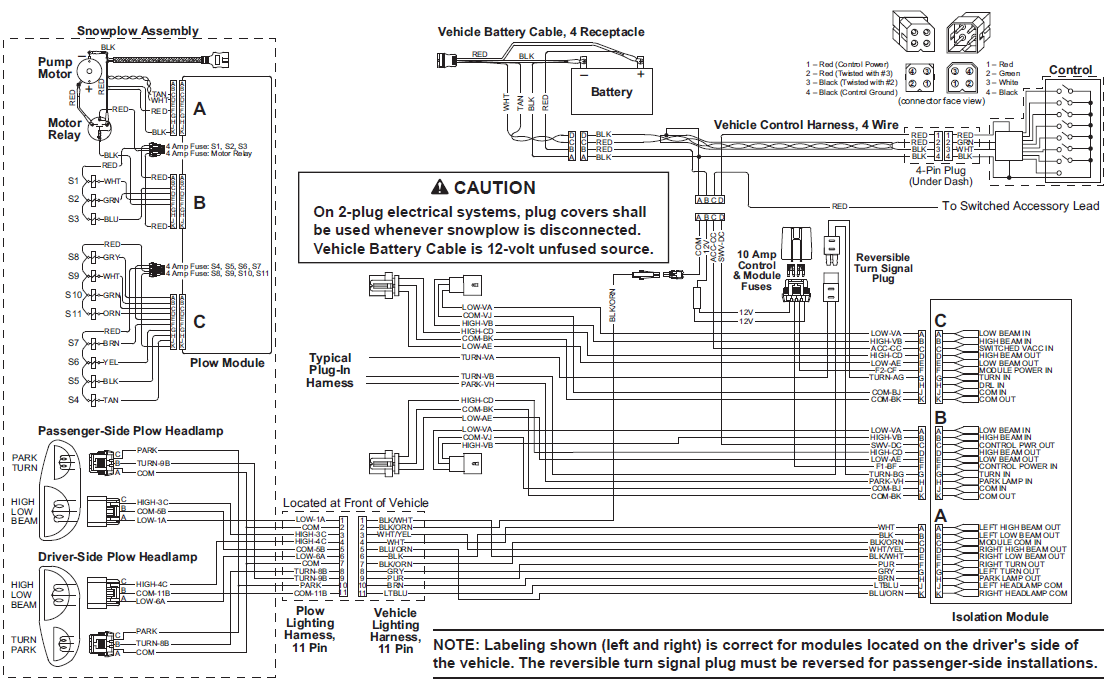
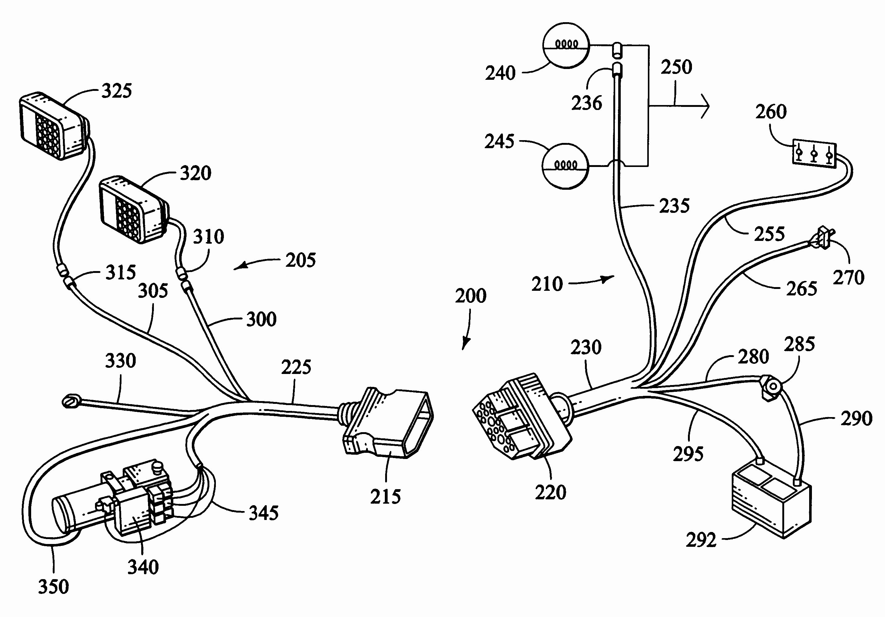
Western plow wiring diagrams are essentially blueprints that depict the electrical layout of the plow. They showcase the various components, including the solenoid, motor, lights, and control box, along with the connecting wires and their respective colors. These diagrams serve as a crucial reference for identifying faults and troubleshooting issues, allowing you to quickly pinpoint the problem areas.
Western plow wiring systems typically consist of several main circuits responsible for different functionalities:
- Plow Motor Circuit: This circuit powers the plow’s motor, which raises and lowers the blade. It usually involves a solenoid that activates the motor and allows for controlled blade movement.
- Light Circuit: This circuit powers the various lights on the plow, including headlights, taillights, and turn signals. It ensures proper visibility and safety during operation.
- Control Circuit: This circuit manages the plow’s operation, allowing you to control the blade’s movement, lights, and other features through a control box or switch.
- Auxiliary Circuit: This circuit powers any additional equipment for the plow, such as a hydraulic pump or a defroster.
Decoding the Wiring Diagram
To navigate a Western plow wiring diagram effectively, it’s important to understand the different symbols and abbreviations used. Each component, wire, and connector will be represented by a specific symbol, and the color of each wire will be clearly indicated. Look for diagrams that provide both a circuit layout and a detailed parts list, facilitating identification and understanding.
Western plow wiring diagrams often use color coding to differentiate individual wires. This color coding helps you quickly identify specific connections and troubleshoot issues. For example, a red wire may indicate a positive (+) voltage connection, while a black wire might signify a negative (-) ground connection. Manufacturers usually provide a legend or table outlining the specific color codes used in their wiring diagrams.
Troubleshooting Wiring Issues
Understanding the wiring diagram is crucial for identifying and resolving electrical issues in Western plows. When facing problems, like a malfunctioning motor or inoperative lights, the diagram becomes your roadmap, guiding you toward the source of the problem. By using a multimeter to test voltages and continuity across different wires and connections, you can pinpoint the faulty component or a broken wire.
When troubleshooting, start by visually inspecting the wiring for any obvious damage like broken wires, loose connections, or damaged connectors. If issues persist, consult the wiring diagram to trace the corresponding circuits and use a multimeter to check for voltage and continuity at different points in the circuit. Never attempt to troubleshoot live circuits without proper safety precautions.

Image: userfixstephanie.z19.web.core.windows.net
Choosing the Right Wiring Components
For repairs or upgrades, choosing the correct wiring components is essential for proper functionality and safety. Avoid using generic wiring that may not meet the plow’s power requirements. Opt for components that are specifically designed for heavy-duty applications, ensuring they can handle the load and withstand the harsh conditions encountered during winter operation.
When sourcing replacement components, always refer to the original wiring diagram or consult with a Western plow dealer for recommendations. They can provide you with the appropriate wire gauge, connector types, and other components to match the original specification and maintain safety standards.
Keeping Your Western Plow Wiring System in Top Shape
Regular maintenance is crucial for ensuring the reliability and longevity of your Western plow’s wiring system. By incorporating these simple tips into your routine, you can help prevent costly repairs and ensure your plow operates smoothly throughout the winter months.
- Visually inspect all wiring for damage and wear. Look for signs of chafing, cuts, or fraying, and replace any damaged sections immediately.
- Inspect connectors for corrosion and tightness. Clean any corroded connectors with a wire brush or contact cleaner. Use dielectric grease to prevent future corrosion.
- Test all wiring circuits with a multimeter to ensure proper functionality. Address any issues identified during the testing process.
- Securely mount wiring harnesses to prevent chafing and movement that can lead to damage. Use tie wraps or zip ties to secure the harnesses to the plow frame or vehicle.
- Store your Western plow in a dry and protected environment when not in use. Protect the wiring from moisture and grime to extend its lifespan.
FAQ: Wiring Diagram for a Western Plow
Q: Where can I find a wiring diagram for my Western plow?
A: You can typically find wiring diagrams for your Western plow in the owner’s manual or online on the Western plow website. If those resources are unavailable, contact your local Western plow dealer or a certified technician.
Q: Can I use a universal wiring harness with my Western plow?
A: While it may seem convenient, using a universal wiring harness is not always recommended. It’s better to use a wiring harness specifically designed for your Western plow model, ensuring compatibility and proper functionality.
Q: What are the essential safety precautions when working on Western plow wiring?
A: Always disconnect the battery before working on the wiring to avoid electrical shock. Use gloves and eye protection to safeguard against possible injury.
Q: How can I learn more about Western plow wiring systems?
A: Consulting online forums, YouTube tutorials, and articles dedicated to snow plow maintenance can enhance your knowledge. Consider taking a certified snow plow repair course for a more in-depth understanding.
Wiring Diagram For A Western Plow
Conclusion
Understanding the wiring diagram for your Western plow is essential for smooth operation and trouble-free winter performance. By deciphering the circuits, recognizing component symbols, and following proper maintenance practices, you can ensure maximum reliability and extend the lifespan of your plow.
Are you finding this information helpful? Do you have any specific questions about Western plow wiring diagrams that you’d like to ask?


